Working schemes for automation of building heating systems
The schemes for the automation of heat supply systems for buildings available for implementation are of interest to many specialists, since they allow them to save money. In addition, such solutions allow you to "upgrade" previously installed heating systems with minimal costs. Today we are considering communal autonomous heating systems that can be applied by our readers in practice. Heating systems automation schemes can be implemented by analogy and are interesting in terms of their organization.
Automation of a two-pipe heating system
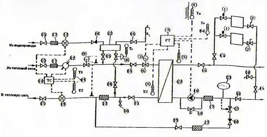
The first automation option is offered for a two-pipe heating system, subject to independent connection to heating networks. In this case, the disclosed in detail in publications closed hot water supply system using secondary heat exchange circuits. It is assumed that all systems are connected to central heating and water supply and regulate the consumption of water and, accordingly, heat.
The main functions of such systems include:
- regulation of the water temperature in the DHW circuit;
- control of the temperature of the coolant in the heating system;
- regulation of differential pressure in heating circuits;
- regulation of differential pressure at the entrance to the apartment heating system;
- commercial metering of heat and hot water consumption;
- independent automatic feeding of the heating system;
- the ability to change the temperature of the heating agent and hot water supply by the user.
Automation of a two-pipe system connected to heating networks
Automation schemes for heat supply systems of a two-pipe heating system when connected to central heating networks and a closed DHW system have the following features:
- the temperature in the rooms is regulated by radiator thermostatic valves with high resistance valves;
- on the "return" there are shut-off valves for shutting off and repairing radiators without draining the coolant of the entire system;
- at the entrance, the system is connected to an additional water heater, for example, an electrode boiler. This is implemented to ensure comfortable heating characteristics during the period when central heating is turned off or its volume is insufficient;
- an additional hot water heater is not provided;
- the heating system is connected to a forced circulation pump with a bypass valve to control the parameters of the coolant at the points of consumption. The bypass valve is necessary to ensure the normal operation of the pump with closed radiator valves and a sealed expansion tank, as well as with a closed make-up solenoid valve;
- the system allows you to control the temperature in the room depending on the outside air temperature with the help of a regulator, in turn, with a control control valve on overheated water by pulses received from the outside air and inside air temperature sensors, as well as the heat carrier;
- the temperature rise is monitored by installing the sensor after the heater, monitoring the data above the threshold value and decreasing the parameters;
- the DHW temperature is controlled by direct-acting valves, including those used to protect against differential pressure in the heating networks of the internal system.
- control valves also exclude the transmission of vibrations to the public heating network and the DHW system. A balancing valve is installed at the inlet to control pressure drops;
- a heat meter is installed at the entrance to account for the heat consumption by the consumer. The heat meter will be equipped with an ultrasonic flow meter and temperature sensors to control the parameters of the heat carrier supplied by public utilities. They, in turn, are connected to a heat flow meter;
- the heat calculator provides data by processing the data of the vane impulse flow meters.
Automation schemes for heat supply systems also provide for shut-off valves, installation of mechanical strainers and check valves that prevent hot coolant from flowing back into the communal system.
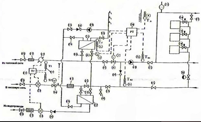
Automation of a one-pipe heating system of a multi-storey building with dependent connection to heating networks and a closed DHW system
The single-pipe system of vertical type according to the project has closing sections. It is equipped with radiator valves with thermostats to maintain the microclimate parameters. Balancing valves are installed in the risers, which make it possible to control pressure drops in the external communal system and ensure the flow rate of the coolant in the heating circuits. This, as we considered earlier, is expressed in uniform heating of all radiators in the contour.
The constituents
The coolant temperature changes proportionally relative to the outdoor air temperature by controlling the speed of the circulation pump connected to the make-up unit. The mixing unit also includes:
- pump;
- a jumper, providing for the overflow of water from the "return", in order to mix and achieve a predetermined temperature. It is connected after the boiler generator and the electrically driven control valve on the supply pipeline, which is controlled by a digital two-way control valve;
- the digital valve also receives data from temperature sensors in the supply and return lines of the pipeline, as well as from an outdoor air sensor;
- this regulator also maintains the air temperature according to user scenarios set on the control system;
- the DHW system is equipped with a secondary heat exchanger and a circulation line with a pump. Temperature support is carried out in combination with the operation of the temperature sensor using the second channel of the regulator, which also controls the motor valve on the heated coolant pipeline;
- a balancing valve is also installed at the inlet, which protects the system from the propagation of oscillations of their communal system and vice versa;
- DHW is equipped with its own water heater and circulation pump in case there is no hot water;
- the DHW temperature is maintained using a regulator valve temperature sensor using the second regulator channel that controls the motor valve on the coolant;
- a heat meter is installed at the entrance to account for the heat consumption by the consumer. The heat meter is equipped with an ultrasonic flow meter and temperature sensors to control the parameters of the heat carrier supplied by public utilities. They, in turn, are connected to a heat meter;
- the heat calculator gives out indicators, processing the data of the vane impulse flow meters.
Automation schemes for heat supply systems also provide for shut-off valves, installation of mechanical strainers and check valves that prevent hot coolant from flowing back into the communal system.
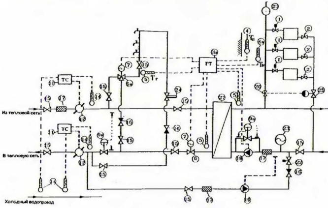
Scheme of automation of the heating system of a multi-storey building with a two-pipe system, with independent connection to utilities and an open DHW system
To control the climatic parameters of heating, the radiator circuits are equipped with high-resistance thermostatic valves. Return lines involve the installation of shut-off valves to shut off the radiator without draining the system.
A balancing valve (automatic) is installed on each riser, complete with a manual shut-off valve to shut off the system as a whole and adjust the pressure drops resulting from fluctuations in the external communal system. The connection is made through an electrode heater, which provides the parameters of the system with a cold external heat carrier.
The heating circuit is equipped with a circulation pump for forced circulation and also for regulating the temperature in the radiator circuits. A differential pressure regulator is installed in the circuit. It ensures the stability of the pump with closed thermostatic valves on the radiators and a sealed expansion tank.
The make-up unit is equipped with a make-up pump and a solenoid valve with a pressure sensor.
Climate control
The heating medium temperature is regulated in proportion to the outdoor air temperature using digital control valves. The regulator implies the control of the electric drive of the control valve on the "return". It is installed after an additional water heater. The control is carried out according to pulse data received from the temperature sensors of the outside air, in the room and the heat carrier. The control valve also controls the set range of the heating medium temperature, corresponding to the set schedule.
DHW
The DHW temperature is maintained thanks to a temperature sensor using a second control valve on the second channel, which also controls a three-way valve connected to an electric actuator on the supply pipeline.
The temperature is regulated by a return temperature limiter. A balancing valve is also installed at the inlet to protect the system from the propagation of vibrations and the utility system and vice versa.
Teploschetikich
At the entrance, the designers install a heat meter to measure the heat consumption by the consumer. A heat meter is installed, complete with an ultrasonic flow meter and temperature sensors to control the parameters of the heat carrier supplied by public utilities. It, in turn, is connected to a heat meter.
The calculator provides data by processing the data of the vane impulse flow meters.
Automation schemes for heat supply systems also provide for shut-off valves, installation of mechanical strainers and check valves that prevent hot coolant from flowing back into the utility system.
Alphanumeric designations on automation diagrams
1-1a - pre-regulated radiator valve;
2 - radiator shut-off valve;
3, 3a, 3b - outdoor and indoor temperature sensors;
5 - coolant temperature sensor in the supply line and on the "return", installed after the boiler generator;
6, 6a - control valves;
7 - geared electric drive;
8 - direct temperature regulator;
9, 9a - pre-set valve for differential pressure regulation;
10 - bypass valve;
11 - heat meter;
12 - ultrasonic flow meter;
13 - vane flow meter with pulse output;
14 - heat meter temperature sensors;
15 - shut-off valves;
16 - check valve;
17 - mesh filter;
18 - drain cock with a hose nozzle;
19 - pump for forced circulation;
20 - flow regulator (limiter);
21 - automatic air vent;
22 - electromagnetic valve with pressure sensor;
23 - expansion tank;
24 - coolant temperature limiter on the "return";
25 - balancing valve (automatic);
26 - shut-off and measuring valve;
27 - water heater;
28 - air heater (air heater);
29 - fan;
30 - air damper;
31, 31a - connecting elements for radiators;
32 - programmer;
33 - boiler generator;
34 - motorized valve-switch with a returnable spring;
35 - room thermostat;
36 - thermostat for hot water supply;
37 - thermostat for protection of the air heater at low temperatures (protection of the system from freezing when the heating is turned off).
Order a building heating automation project
Order an automatic boiler room for buildings


