Pellet cascade boiler rooms with climate control PLUM
As is known, cascade connection of boilers is implemented to increase the power of a boiler room, when the entire heating resource is initially not needed, but is connected on demand. As a result, using program-controlled pellet boilers, it is possible to obtain heating modules with a total power of 2.5 MW. Considering that all FOCUS industrial and semi-industrial pellet boilers are equipped with an EcoMax series microcontroller from the Polish company PLUM, these boiler rooms will support fine-tuning of climate control.

Scaling climate control functions: from microcontroller to large systems
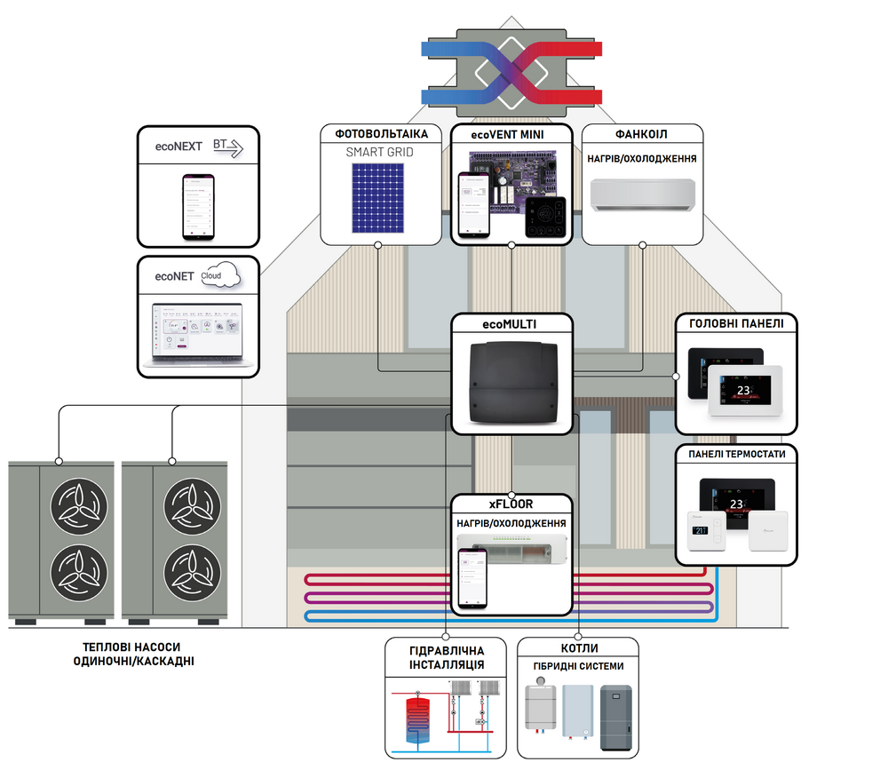
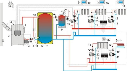
Cascade boiler houses with pellet-type climate control can serve offices, shopping centers, factories, supermarkets and apartment buildings in communal boiler houses. It is possible to deploy systems of any complexity. This is achieved through additional heating circuits and the installation of expansion cards for climate control. An example of scaling the functionality of room temperature control functions is shown in the illustration. This is implemented using special expansion modules, connected to the main microcontroller of the boiler or a system that controls the cascade connection of boilers.


How is climate control organized?
De facto, the climate system is an add-on or parallel interface that monitors the operation of boiler, heating and metering equipment. Cascade boiler rooms with climate control are served by a system that can be expanded thanks to expansion modules, just like a heating system. Each touch panel in the system programs the functions of its heating circuit; as a result, the data is collected and transmitted in the form of commands to the boiler microcontroller.
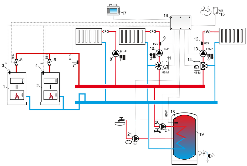
An example of hydraulic decoupling for these purposes is shown in the diagram; large systems expand such circuits and separate their functions. In heating systems, both individual circuits are serviced centrally and apartment systems to expand functionality temperature control of a separate heating module.


